Thermal Control System
Main Purpose of the Design:
The system consists of two thermal capacitances, C1 and C2. Heat is supplied to the first capacitance, C1, at a rate q1(t) by a heater, while heat is lost to the environment at the left end. The first capacitance is thermally connected to the second capacitance, C2, through a thermal resistance, R2. The second capacitance is further connected to the environment on the right side, which is maintained at an ambient temperature, θa. Apart from the thermal resistances R1, R2, and R3, the enclosure is assumed to be perfectly insulated.
Design Implementation:
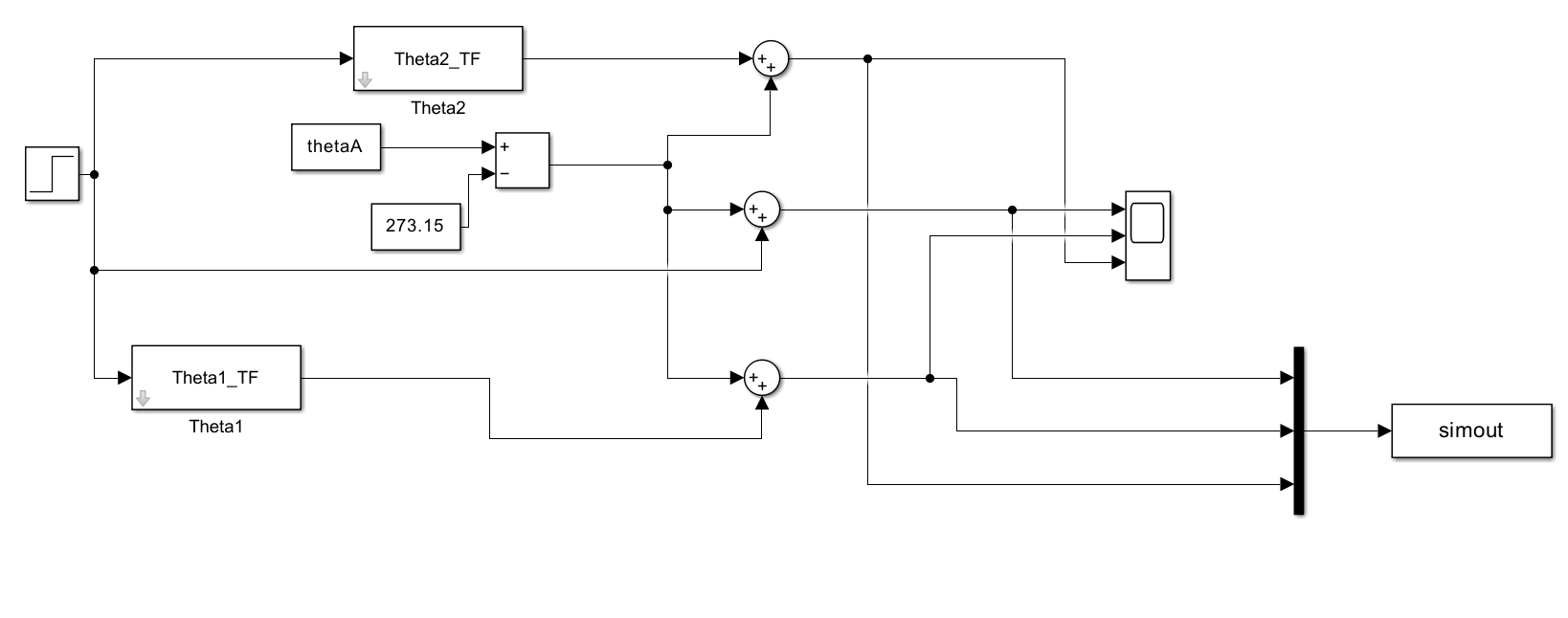
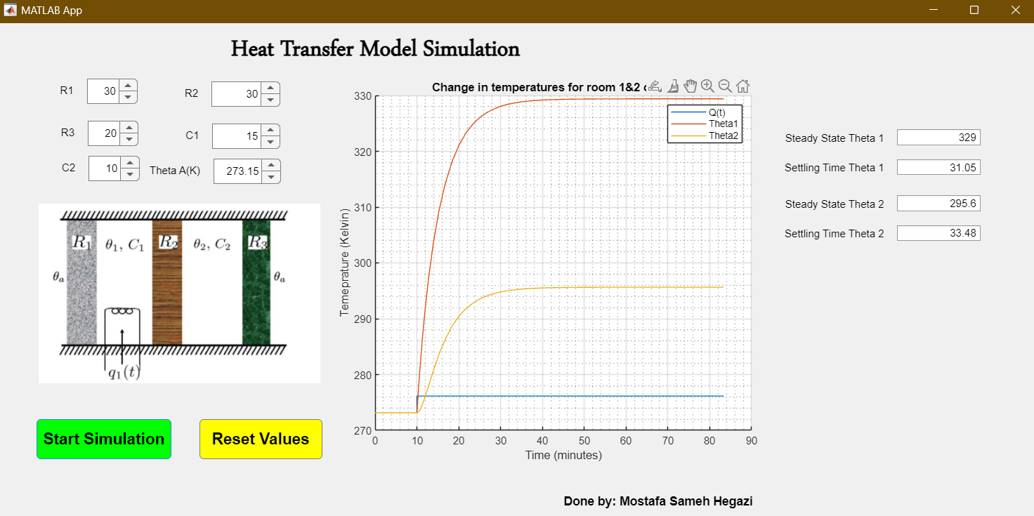
I utilised Matlab and Simulink functionalities to simulate the system and predict its response to a step input signal. I rewrote the transfer functions using Matlab, designed the closed-loop block diagram using Simulink, and, afterwards, designed a Matlab GUI to allow the user to change parameters and interact with the model.